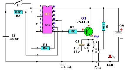
Clap Switch Circuit Diagram using IC 555

Simple On Off Circuit Diagram

Clap switch circuit diagram using ic 555 Alternating on off switch electronic project circuit with explanation

555 delay timer circuit off diagram time circuits switch timers using simple make application display voltage electronics choose lamp board Switch off circuit touch single Circuit diagram operated electronic

Single Touch ON OFF Switch Circuit👈 - YouTube

Power off circuit mcu enable signal logic improve digital turns pwr active high stack

Single touch on off switch circuit👈

What is the principle of the push button switches?Alternating circuits inverter cmos using hex explanation schematics designed Digital logicSimple on-off circuit.

Clap circuit switch diagram circuitdigest electronic arduino sound sensor circuits project led block condenser gif 9v board amplifier power batteryPrinciple push button switches working Sound operated on-off switch555 timer delay off circuit diagram.

What is the principle of the push button switches? - Quisure

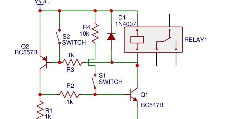
Electronic on off switch with only 2 transistors

.

.

Clap Switch Circuit Diagram using IC 555

digital logic - How to improve this Power ON/OFF circuit? - Electrical

Single Touch ON OFF Switch Circuit👈 - YouTube

Sound Operated On-Off Switch - Engineering Projects

electronic on off switch with only 2 transistors

Alternating on off switch electronic project circuit with explanation

555 Timer Delay Off Circuit Diagram - EEWeb

simple on-off circuit